Architecture of a Microcomputer
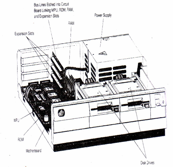
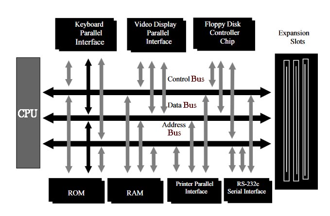
The most modern microcomputers utilize a motherboard, a single large circuit board containing the microprocessor unit (MPU) also known as Central Processing Unit (CPU), ROM, RAM, and other associated circuits. These elements are linked through a series of parallel metal lines etched into the motherboard called the system bus. The system bus carries three types of information; these are: control, address, and data. Control information is carried by a number of control lines, addresses by a number of address lines and data by data lines.
The width of the bus is important to the performance of the computer. The wider the bus, the more information can be carried at one time and the greater the throughput of the system. Most 16-bit microcomputers use 8 or 16-bit buses, 32-bit microcomputers use 8-bit, 16-bit, and 32-bit buses, while 64-bit microcomputers use 16-bit, 32-bit and 64-bit buses.
A number of slots provide access to the system bus (Figure 3.1). Input/output devices can be connected to the microcomputer through the slots and appropriate interface circuit boards. The slots can also be used to expand the RAM capability of the microcomputer.
I/O Interface
Communications between an input/output device and the MPU take place through an interface. The interface converts the data from a form used by one of these devices to a form acceptable by the other. It must also adjust for speed differences between the processor and the other device. The interface circuits of microcomputers correspond to the I/O control units used on larger computer systems.Two general types of interface devices in use are serial and parallel. A serial interface transmits data as a string of bits, one bit after the other, over a single wire. A parallel interface transmits data byte by byte through a multi wire cable. Parallel interface devices are faster, but are more costly. The interface must match the requirements of the device it supports.
Figure 3.2 illustrates some of the I/O devices generally connected to a microcomputer. These devices are linked through a common system bus. Communications between these devices take place over this bus, under control of the processor. Thus, the bus while carrying data from a disk device to memory, for example, cannot carry data to or from the keyboard, monitor, or any other I/O device.
Some microcomputer systems use a separate microprocessor to handle I/O operations. This frees the MPU to perform non-I/O operations on other programs while the separate processor handles the I/O operations for the current program.


0 Comments